What is reverse engineering?
Reverse engineering is a process where a physical part is deconstructed and measured in order to understand its design, how it works, and how it was made. This could be anything from a massive aircraft carrier or architectural structure, all the way down to a Swiss watch’s tiny set of interlocking gears.

Introduction
As opposed to a conventional design workflow, where you’re “starting from nothing” and creating a product from the ground up, in reverse engineering you start with an existing machine or component and work backwards, disassembling it either physically or digitally, part by part, or layer by layer, one step at a time.
The goal of reverse engineering is typically to create a useable 3D CAD model, and when done right, reverse engineering gives you the power to take this design information and achieve a number of objectives:
- Recreate legacy devices and parts, including via additive manufacturing technologies
- Conduct failure analyses on parts and machines, redesign as needed
- Deeply analyze the positives and negatives of a competitor’s product
- Easily replicate parts that are out-of-stock, extremely expensive, or have long wait times
- Improve the performance of any existing parts and systems
- Use the design information as a basis for creating an entirely new product
- And more
How to capture data for reverse engineering
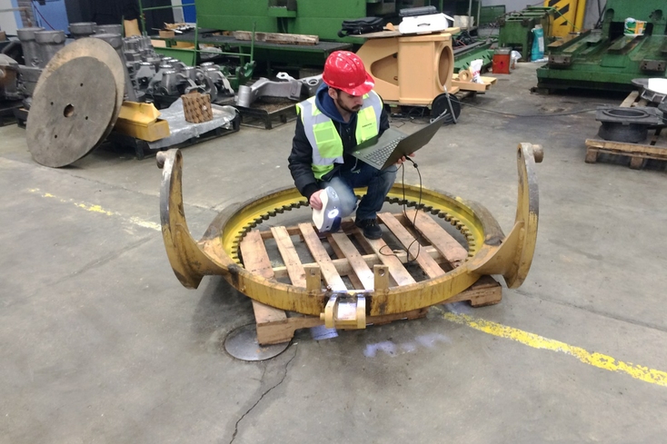
3D scanning a decommissioned circular assembly of a construction machine with Artec Eva. The 3D scans were later exported into Geomagic Design X reverse engineering software and served as a reference model for creating a solid model, which was then used to manufacture a replacement part.
Although other methods of capturing data for reverse engineering are occasionally employed, whether manual or digital, by far the most popular in use today are 3D scanning, CMM machines, and CT scanning. Each method has its respective pluses and minuses, depending upon the application, as well as your budget, experience with the chosen technology, and available project time.
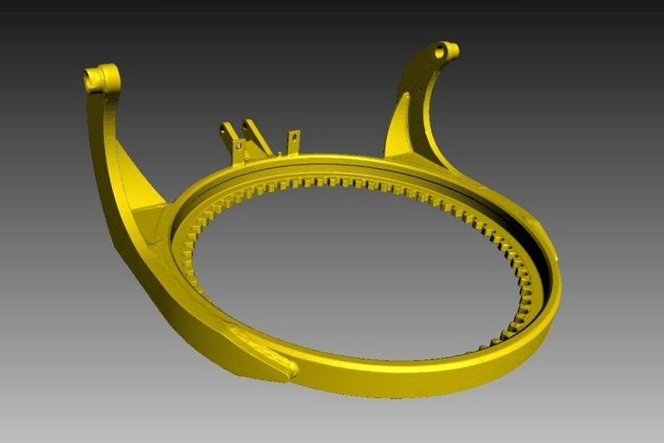
A 3D mesh model of the circular assembly created from Artec Eva scans
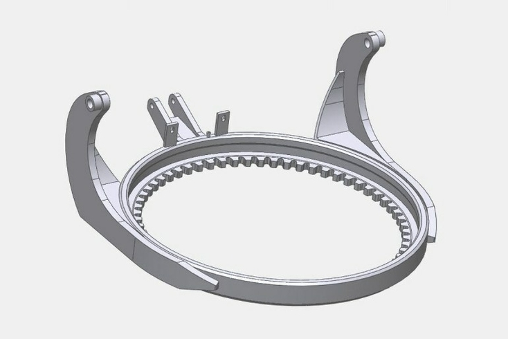
A CAD model of the circular assembly, ready for reverse engineering use
CT scanning
An effective way to capture both external and internal measurements of an object, CT scanning is normally thought of as a serious tool for medical diagnostics. But it’s also a viable solution for reverse engineering, given the right circumstances and applications. By emitting X-rays through an object, a CT scanner is mostly unaffected by line-of-sight challenges, enabling the capture of internal features, porosity, and other voids. CT scanners typically work either by emitting a cone of X-rays through a part, or a slice of X-rays through the part, and then assembling the many different layers of data together into a full 3D model.
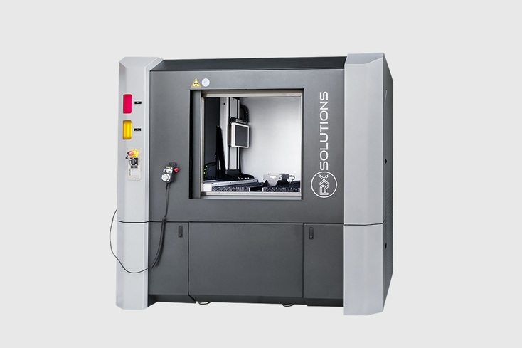
EasyTom industrial CT scanner, image courtesy of CyberOptics Corporation
But CT scanners aren’t without drawbacks. Since they utilize radiation to penetrate objects being scanned, the object you’re capturing will need to fit inside the CT scanner’s special chamber, which is firmly sealed to prevent radiation leakage and injury to operators. This limitation rules out scanning the majority of medium- to large-sized objects.
Key point
While a CT scanner’s forte lies in its ability to capture both external and internal surfaces of an object, as of yet this technology is applicable only to a narrow range of industrial objects.
Besides their lofty price tags, reaching upwards of $250,000 or more for a dependable unit, and requiring specially-trained operators, CT scanners can occasionally suffer from defects when scanning metal objects, or even objects with metal components. The reason for this is that metal absorbs and scatters x-rays as they strike the surface of the part or section in question, resulting in streak artifacts on the scan. This significantly lowers the scan’s accuracy. Low-density metals, such as aluminum, are considerably easier to scan than ferrous materials such as steel.
In short, unless you’re working with relatively compact, entirely plastic or other low-density-metallic parts, CT scanning can demand hours of extra time spent in scan processing, simply to remove the artifacts and attempt to restore your object’s actual measurements, and possibly be unable to scan the object at all due to part size or density of the material.
Contact measurement (CMM machines)
CMM machines are known to deliver exceptional degrees of accuracy, both for inspection and reverse engineering. They make use of a pre-programmed or operator-controlled probe to record a series of XYZ coordinates across the surfaces of objects, essentially building a 3D representation of the visible geometries of the object step by step.
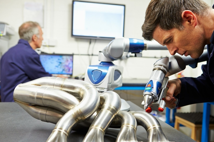
Two engineers using a CMM to inspect a machine component
Assuming that the technology is used within its spectrum of effectiveness, a CMM machine can be a costly yet powerful solution for capturing objects of many different sizes and materials.
Most CMMs are extremely heavy devices, usually mounted in place and difficult if not impossible to transport around a warehouse or company if the need arises. That rules out being able to conduct scanning at a client’s site or taking the CMM with you on an overseas flight if the accuracy required is in excess of what portable CMMs can accomplish. In addition, CMMs require trained operators and substantial time investments for setup and reprogramming, and can suffer greatly from accidental kicks, bumps, and vibrations that are likely to ruin a measurement project if not detected.
Key point
Direct contact with a surface ensures exceptional accuracy of 3D data collected with a CMM’s touch probe. The handicaps here include the machine’s inability to inspect sections of the surface its probe cannot physically access, risks of inflicting permanent damage to various materials, and a low speed of data capture, to name a few.
Since most commonly-used CMM probes all involve repeated contact with the object being measured, it’s worth mentioning the potential risks of damage as well as inaccuracies. A whole range of materials can incur damage from a CMM probe, whether scratches, scrapes or blemishes. This heightened risk of defects is absolutely unacceptable when working with expensive or priceless objects, including those in museums, private collections, and other high-price-tag items.
In terms of precision, when coming into contact with soft surfaces such as rubber or silicone, the probe can easily deform the part, resulting in at best an inaccurate measurement, if not permanent damage. Complicating matters further, if the object you’re measuring has recessed surfaces or other difficult-to-reach sections, and if the CMM probe is not able to reach them and make sufficient contact, then these places will have to be rebuilt manually via CAD, thus introducing some extent of variation from the original.
3D scanning
For countless thousands of users around the world, professional desktop, handheld, and tripod-mounted 3D scanners are a trustworthy choice for reverse engineering applications and much more. Whereas CT scanners and CMM machines feature high price tags, boat-anchor-like degrees of immobility, and steep learning curves, the best 3D scanners are entirely the opposite.
Scanning with structured light
Structured-light 3D scanners capture objects by first beaming down a strobed pattern of light upon the surfaces of what they’re capturing. When the light bounces back to the scanner’s sensors, the distortions in the pattern made by the object’s structures are detected and converted into an accurate digital representation of the object in the scanner’s software. This digital replica, in the form of a 3D polygonal mesh, can then be used to create a CAD model of the object being reverse engineered.
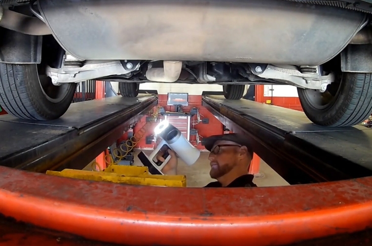
3D scanning the undercarriage of a Volvo XC90 with Artec Leo to reverse engineer the SUV’s exhaust system
One of the primary benefits of using structured-light 3D scanners is their speed of capture. In contrast with either CMM machines or photogrammetry, the latest professional structured-light 3D scanners can capture even large objects in mere minutes, with submillimeter degrees of accuracy, and no contact required. Depending upon the scanner, as you sweep its beam of light across what you’re scanning, you’ll be capturing anywhere from 1 million to 3 million points per second.
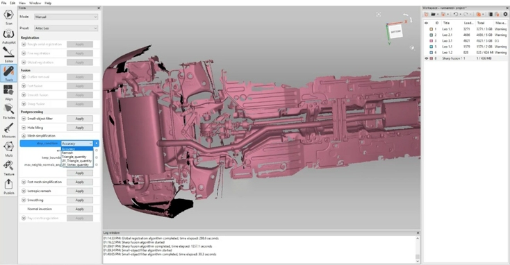
Processing the scan of the Volvo XC90 undercarriage in Artec Studio
With a structured-light 3D scanner, you have immediate feedback on the laptop or scanner screen that you’ve captured every section of the object or area you’re scanning. If you missed any spots, you’re simply a wave or two of the scanner away from capturing it in full.
Last but certainly not least, structured-light 3D scanners are perfectly safe for use, not only for the person doing the scanning, but also onlookers as well as those being scanned. This is one of the foremost reasons why structured-light 3D scanners have been embraced so readily throughout the field of healthcare.
Laser light scanners for larger objects and entire scenes
Tripod-mounted 3D laser (LiDAR) scanners can be grouped into two separate categories: time-of-flight and phase-shift. Time-of-flight (ToF) LiDAR scanners work by beaming laser light onto an object or area, either indoors or outdoors, and then calculating the exact distance to it by measuring the time it takes for the light to bounce back to the scanner’s sensor. The sensor also detects the strength of the light received.
Phase-shift LiDAR scanners, on the other hand, emit a steady laser beam in several different phases. When the laser light bounces back to the scanner's sensor, the shifts in the light are analyzed via specific processing algorithms and used to determine the precise distance between the scanner and the object and/or scene being captured.
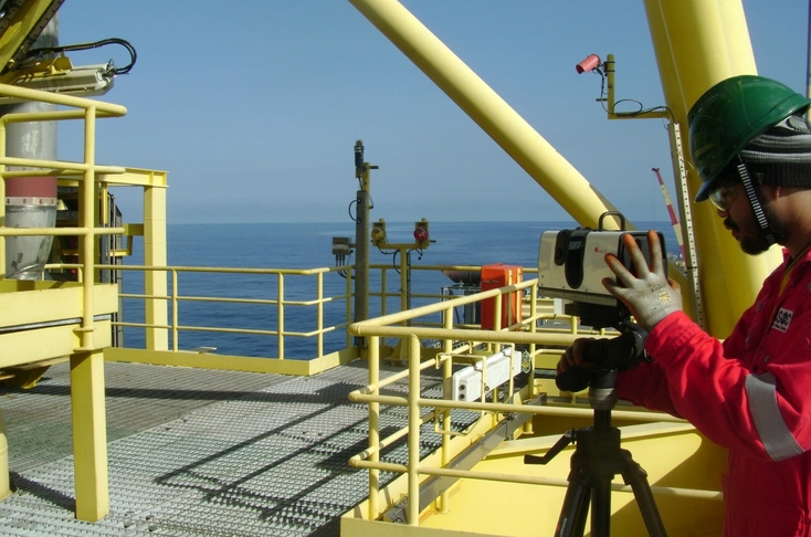
Preparing the tripod-mounted Artec Ray for 3D scanning the deck of an offshore vessel
From the data received, a digital rendering of the object or area is created in the form of a high-resolution point cloud. These point clouds can then be turned into polygonal meshes by the scanning software. Following this, the meshes can be used for a variety of purposes, including generating CAD models for reverse engineering, virtual fly-throughs, building floor plans, etc.
Laser-based long-range 3D scanners can easily capture large to truly massive objects and scenes with incredible accuracy and precision. With a working distance from one meter to more than 100 meters away, the best scanners of this type have been used to create metrology-grade 3D models of cars, jet planes, superyachts, and even entire factory floors.
With robust 3D scanning software, the scan data from a long-range laser scanner can easily be merged with that of handheld 3D scanners to create a unified 3D model which encompasses every possible geometry and surface of the object or scene. Some examples of this are reverse engineering a modern airliner by using a long-range laser scanner to capture the entire architecture of the plane, while employing a handheld 3D scanner for the instrument panels and intricate details throughout the cockpit and cabin.
Ease of use, unrivalled scanning possibilities
Long-range laser, desktop, and handheld structured-light 3D scanners are so easy to use that even students can learn how to capture objects large and small in just hours. Their portability makes them easy to use in-house, outdoors, or even at faraway client sites.
Compared to the lengthy scanning sessions required by both CT scanners and CMM machines, desktop and handheld 3D scanners can capture the same objects in a fraction of the time, thus minimizing operator fatigue and boosting your productivity. Tripod-mounted laser scanners are even more hands-free. You simply place the tripod in the desired scanning position and activate the scanning sequence.
Key point
Indispensable tools for the vast majority of reverse engineering tasks, the best of 3D scanners are fast, safe & easy to use, and capable of capturing a broad range of objects, from small to large, with submillimeter accuracy.
Repeat as needed, depending upon the characteristics of the object or area you’re capturing, for full coverage of all surfaces, including recessed sections and components.
All things considered, when it comes to reverse engineering anything from a diamond ring all the way up to king-size objects such as heavy machinery, aircraft, buildings, and more, professional 3D desktop, handheld, and long-range laser scanners are proven solutions that give you the ability to get the job done.

Reverse engineering with 3D scanning: applications
Let’s start off by highlighting three examples of how reverse engineering with 3D scanning is being carried out in several industries: auto customization, agricultural equipment, and high-performance bicycle design.
West Coast Customs
Whenever this world-famous auto customization shop in California needs to recreate legacy parts or bring to life one-off fenders, grills, headlights, bodywork, or other parts for their next-level design projects, they use professional handheld 3D scanners in conjunction with Geomagic Design X and SOLIDWORKS software.
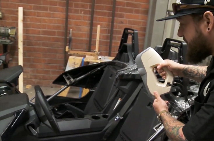
West Coast Customs design expert scanning a Polaris Slingshot vehicle with Artec Eva
It’s a quantum-leap from the lengthy manual process they relied on in the past, with its extensive measuring and re-measuring using tape measures and calipers. Many if not most auto parts are challenging to accurately measure via linear methods such as these, while the best 3D scanners capture even the most complex surfaces and geometries without difficulty.
These easy-to-use scanners let West Coast Customs capture whatever parts or objects they need to customize, with up to 0.1 mm accuracy, in just minutes. After that, they export the scans over to their CAD system for design modifications that same day. From these “digital blueprints” they can then 3D print or CNC mill whatever parts they need.
Taylor Attachments
Clients with legacy farm equipment have contacted this UK designer-producer of custom replacement headstocks for years. These are mounts for attaching a wide variety of farm machinery, such as backhoes, forks, saws, bale stabbers, and more. Years ago, Taylor’s specialists needed 7-12 hours to reverse engineer each piece of legacy equipment, using manual measurement methods such as pens, paper, rulers, and calipers to painstakingly trace their measurements out on paper and cardboard, before creating several prototypes for testing and modifications.
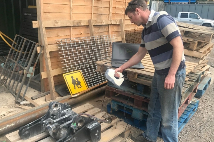
3D scanning a headstock with Artec Eva at Taylor Attachments
It was a system full of second-guessing and fine-tuning just to make things right, with up to 2-3 weeks needed for each unit. Today their workflow looks entirely different. In 20 minutes, they scan the entire headstock in high-resolution 3D with a handheld 3D scanner, the Artec Eva. Another 20 minutes in Artec Studio software results in a fully processed 3D model. From that point, the 3D model is exported to SOLIDWORKS, where the final touches are made before sending the CAD model on to a partner for laser cutting.
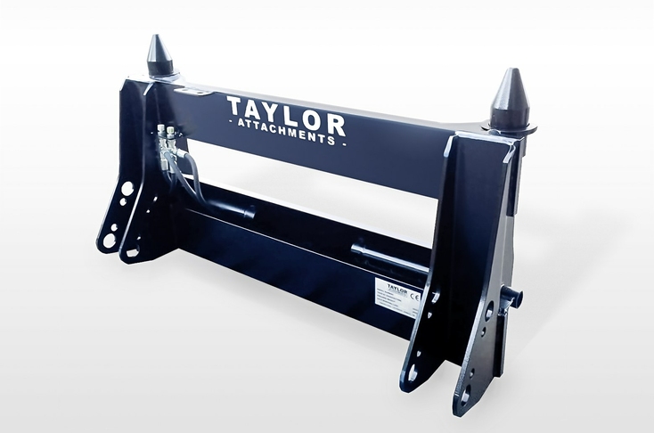
Taylor Attachments replacement loader headstock ready for installation
The end result is having everything done with precision from start to finish in less than 24 hours. Compared to the old method, they’re now saving themselves days if not weeks of work, not to mention untold amounts of frustration.
The Vorteq WX-R high-performance track bike
From the moment this UK-based sports performance company set its sights on creating the fastest track bicycle on the planet, they knew they’d depend on their 3D scanners to make it happen. To get started, Vorteq’s engineers reverse engineered a range of professional cyclist’s bicycles using their handheld 3D scanners to capture each bike in under one minute.
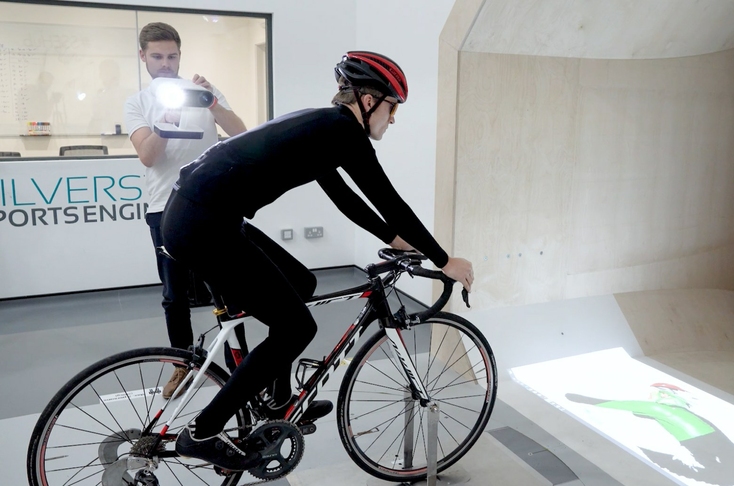
3D scanning a rider and bike in a wind tunnel with Artec Leo
These submillimeter 3D scans were then turned into 3D models and analyzed in the company’s CFD (computational fluid dynamics) system to study the amount of aerodynamic drag for each bicycle. The engineers then made structural adjustments to the 3D models, enhancing their performance to the max. After that, they distilled the best structural aspects from all the bikes and brought them together into one design.
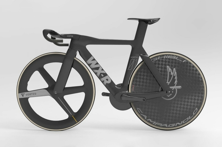
The Vorteq WX-R track bike (image courtesy of Vorteq)
Despite Vorteq’s engineers having years of experience with a full array of metrology tools, they choose handheld 3D scanners as their go-to solutions on a daily basis. For the WX-R bike project, they understood that trying to accurately measure a professional racing bike’s complex surfaces and parts using tape measures and rulers would be an hours-long event awash with double-checking.
By turning to their 3D scanners for reverse engineering, they met their project deadline and just weeks later, the first WX-Rs rolled out of the factory. Next stop: the Olympics!

Reverse engineering with 3D scanning: the process
While workflows certainly vary from company to company, a general sequence of tasks for reverse engineering with 3D scanners can be described as follows:
Preparing the object for scanning
If your object has any clear or highly-reflective parts, you may need to spray them with a fine-grain, matte scanning spray before starting the scan. This will improve accuracy and can significantly reduce your scan processing time. Depending upon the length of your scanning project, you can choose either a vanishing spray that will evaporate in hours, leaving no traces behind, or a non-permanent spray, for longer-term projects, which will then need to be washed off by hand.
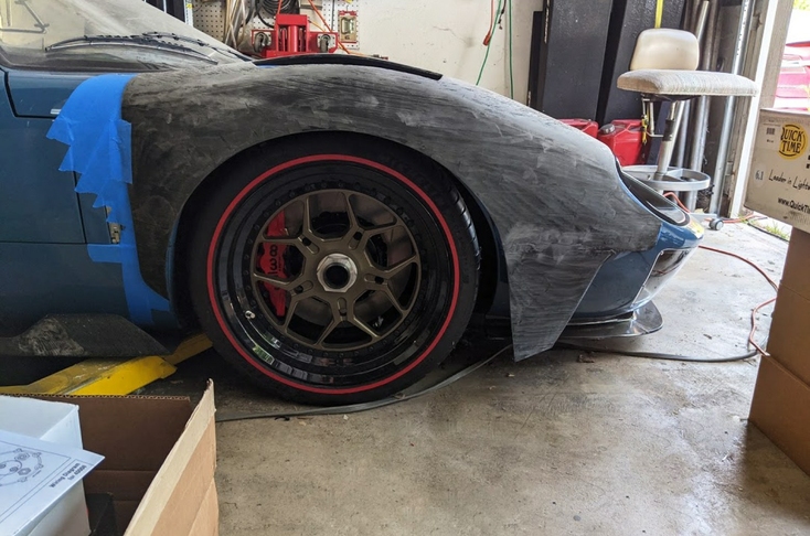
Highly-shiny front end of a Superformance GT40 ready for scanning with Artec Eva
Now is also the time to position your object for scanning. For smaller objects, that can mean placing the object upon a turntable, or in the case of a desktop 3D scanner, mounting the object on the scanning platform, perhaps with an adhesive material such as Blu Tack. Unless you have a wireless handheld scanner at hand, make sure there’s enough room to maneuver around the object while scanning, without letting any cables or other equipment restrict your movement.
Capturing large and extremely large objects will very likely demand the use of a long-range laser scanner. In that case, it’s all about positioning the scanner in relation to the object or area being captured. Make sure to relocate the scanner to new vantage points that allow for sufficient overlap in scan data and full coverage. By reviewing your scans in the scanning software while still onsite, you can easily identify and rescan any places that weren’t fully captured as a result of your object or scene having recessed or occluded surfaces.
3D scanning the object
Capturing your object can take anywhere from a handful of seconds to an hour or more, depending on the capabilities of your 3D scanner and the size/complexity of the object you’re scanning. It must be said that one scanner can’t be the best solution for every possible reverse engineering project.
For example, trying to capture an heirloom jewelry set with a handheld 3D scanner can be feasible, especially one that delivers submillimeter-quality results, but if you have shelves full of such jewelry, and need to scan such objects on a regular basis? Then it might be better to consider an automated desktop 3D scanner designed to capture very small objects.
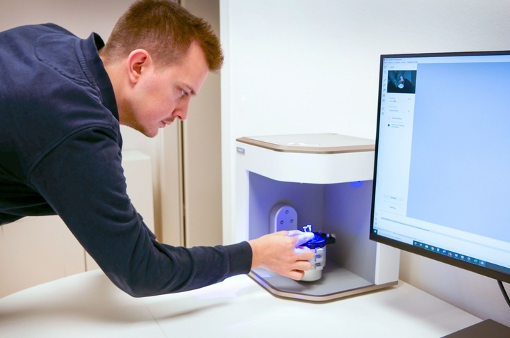
The Artec Micro desktop 3D scanner being prepared for scanning
As well, if you’re set to reverse engineer auto bodies or even motorcycles, you’ll want to have a 3D scanner with a wider field of view and faster capture rate, a device that lets you move around with ease, ideally with no cables or other equipment to tangle you up.
After scanning one side of your object and making sure that you’ve captured all its surfaces, reposition the object as necessary and repeat the process until your object has been fully captured.
In regards to scanning a large or massive object, such as a motor home, construction excavator, or even an Airbus A380-800 airliner, as mentioned above, a long-range laser scanner should be your instrument of choice.
Scan processing, CAD design, and additive manufacturing
Once you’ve captured your object or scene in full with your 3D scanner, then after just a series of clicks and selections, you’ll have a clean, extremely-accurate polygonal mesh of your object ready for the next step. And you’re one step closer to reverse engineering your 3D scan data into a CAD model.
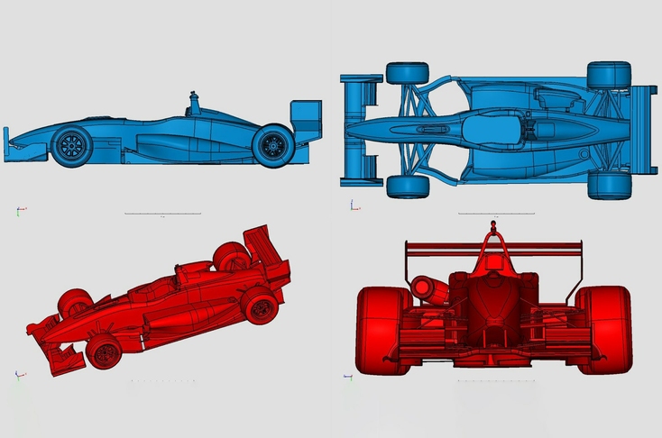
CAD models of a Dallara F399/01 race car, made from Artec Leo scans
If your scanning software offers scan-to-CAD features, you can precisely position your 3D model and begin fitting it with CAD primitives. These are CAD-ready shapes that seamlessly match up with the 3D model’s measurements and geometries, and by fitting your 3D model with them ahead of time, it may already be complete, or at least several steps closer, when you bring it over into CAD.
CAD design work
Once your scan processing is done, you’re ready to export the 3D model over to a reverse engineering CAD program such as Geomagic Design X or Geomagic for SOLIDWORKS. That’s where you’ll finalize the process of using your 3D model as a reference for drawing your CAD model. If you’ve fitted CAD primitives to your model, you can simply export these as CAD objects for use in your reverse engineering software.
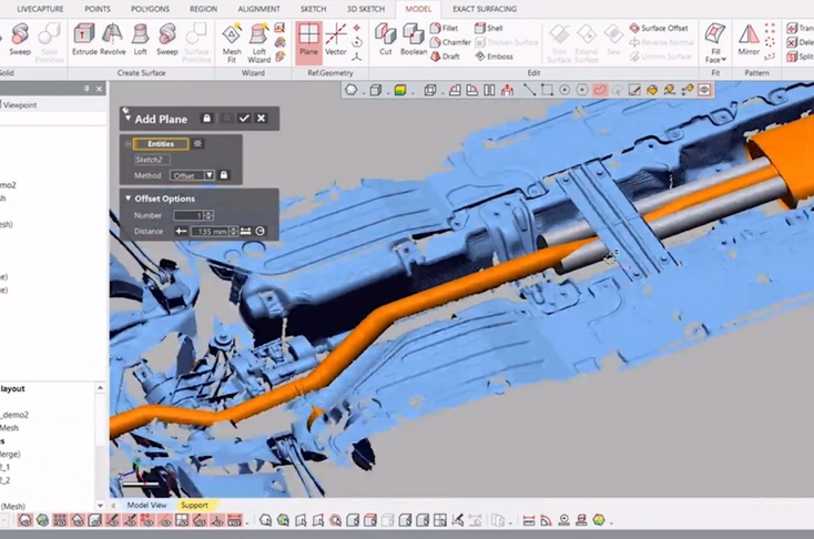
Reverse engineering a new exhaust system for a Volvo XC90 in Geomagic Design X software
Within your CAD system, you’ll have the power to analyze the existing model and customize it as much or as little as you’d like. This includes detecting asymmetries, deformities, or other subtle irregularities that were present in the original object (and possibly not known before!), and then modifying the CAD model to overcome those issues. New features can be added on, and the entire design can be scaled up or down, with adjustments to the shape and volume, and more.
Key point
CAD software gives you the power to customize a 3D model of an object the way you want, test out a new design in a virtual environment, and make all necessary preparations for manufacturing.
If needed, you can also take your CAD model into a computational fluid dynamics or FEA (finite element analysis) system, to test the model under various conditions or stresses, and then decide how to change the physical design or material(s) in order to achieve maximum performance while staying well within established tolerances.
After your design work is done and your CAD model is ready to be brought into the physical world, if you haven’t already, you can choose from a variety of manufacturing technologies. These can include traditional casting and molding processes, CNC milling and machining, as well as additive manufacturing, better known as 3D printing or rapid prototyping.
How is reverse engineering implemented legally?
Without a doubt, professional 3D scanners make it easy to reverse engineer even the most complex objects, yet there are some important considerations to bear in mind. For one thing, if what you’re reverse engineering is trademarked or patented, you can’t simply duplicate and start selling the very same part or object, even if you’re using a different composite, metal, or additive manufacturing process. Well, you can, but then you should also expect a barrage of calls from the original manufacturer’s team of lawyers.
Key point
Before venturing forth on a reverse engineering project, it’s in your (and your company’s) best interests to carefully explore any potential legal or organizational ramifications of your intended use.
Modern intellectual property (IP) laws cover design patents as well as trade secrets, copyrights, trademarks, etc. Simply reverse engineering a design, including using a 3D scanner to do so, does not by itself violate any of these laws. BUT, it’s where you go with the design from there that can mean either staying within the law or stepping outside of it. The experts agree that if you want to be in the clear, then you need to modify that original design. The more, the better, especially when your use will be commercial rather than personal.
During the actual reverse engineering process, multiple prototypes can easily be brought to life and evaluated for further development. To be entirely safe, make sure that your modifications take your design indisputably outside the realm of the original manufacturer’s (OEM) IP rights coverage. With the extensive functionality of today’s best 3D scanning and CAD solutions at hand, it’s fully within your power to do just that.
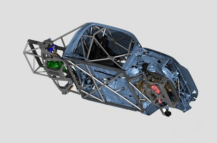
Digital render of Artec Eva scans with custom Tekk Consulting chassis for Brad DeBerti’s “The Performance Truck”
In summary, before venturing forth on a reverse engineering project, it’s in your (and your company’s) best interests to carefully explore any potential legal or organizational ramifications of your intended use. That way, you’ll be able to intelligently put together a plan for how you can reverse engineer a part, series of parts, or machine, and then legally and effectively use the resulting CAD data to accomplish your project goals.
Conclusion
With each passing week, more and more companies and organizations are turning to professional 3D scanners for their reverse engineering needs. Although a variety of other tools exist for the job, 3D scanning has proven itself to be an efficacious synergy of accurate, fast, easy, and affordable.
Whether you need to reverse engineer small, impossible-to-source components that require accuracy well beyond a millimeter, full-sized automobiles or recreational vehicles, or even an entire aircraft hangar, there’s a 3D scanner that will help you get the job done, quickly, easily, and within budget.
Read this next
More from
the Learning center
You can learn a great deal about an object by taking it apart and putting it back together. This process is, in essence, how reverse engineering works. And while dismantling and reassembling can tell you what you need to know about how something was made or how it works – and subsequently, how to replace, improve, or analyze parts – it’s essential to get accurate measurements of the parts. This is when 3D scanning comes into play. And the best way to create reliable CAD models from 3D scan data? Using the best reverse engineering software. With that in mind, here’s our selection of the finest tools ready to come to the rescue.
3D scanning is now more popular than ever, and businesses all over the world are embracing this versatile technology to boost productivity, eliminate unnecessary costs, and create new and exciting products and services.
Looking for a new professional 3D scanner? We know how hard it can be to find the right solution. That’s why we’ve created a checklist of everything you need to weigh up, from specs to practical considerations, to help you identify a product that meets your exact needs.


