Best CAD software for mechanical engineers
Computer Aided Design (CAD) software is used by designers and engineers in different spheres in a whole range of processes. It is a mainstay in the workflows of those working in design, simulation, manufacturing, and many other areas. CAD software is useful not just for providing visual representations of design concepts or drafts, but also for documentation, without which you wouldn’t be able to do things like make patent applications and legally protect designs, or check them for compliance.
Introduction

Computer Aided Design (CAD) software is used by designers and engineers in different spheres in a whole range of processes. It is a mainstay in the workflows of those working in design, simulation, manufacturing, and many other areas. CAD software is useful not just for providing visual representations of design concepts or drafts, but also for documentation, without which you wouldn’t be able to do things like make patent applications and legally protect designs, or check them for compliance.
Over time, CAD software has evolved from being just a set of basic designing and drafting tools to include features that can perform considerably more complex functions. Professional-tier software has modules that can carry out advanced calculations, various types of analyses, and can provide vital information like tolerances, materials, and other technical information.
Specialists in different areas of expertise use CAD software to examine design aspects like aerodynamics, thermal properties, kinematic parameters, stress, and other properties related to their area of expertise.
In this article, we explore some of the leading CAD software available for mechanical engineers. We discuss the considerations to take into account when picking the one for you, and we look at the pros and cons of each, pricing, and main features.
How to choose the best CAD software for mechanical engineers?
Finding CAD software that really fits your needs is sure to save you lots of frustration down the road. It’s tempting to simply go for the best you can afford, but apart from the cost of the product itself, there is the time investment that will be wasted if you choose the wrong software. This might be software that, for example, doesn’t have the right functional capabilities, doesn’t seamlessly slot into your workflow, or even worse, disrupts it.
Also, whatever your level of expertise, there’s a bit of a learning curve for each major platform. So here are some considerations to make and save yourself a few gray hairs as you go about finding the right CAD software for you.
Does it really do the job?
First, ensure that the software features the capabilities that your workflow demands. Whether you are in design, manufacturing, or any range of application scenarios, there will be certain functionalities that you’ll know are crucial for you. For instance, if you have a multi-faceted team, does the software offer options for collaboration? Can you integrate different design aspects, for example electrical and mechanical, in one project and with options for managing different versions? Does the software offer templates and automation to help you speed up your workflow and also standardize your designs?
KEY POINT
Ensure that the software features the capabilities that your workflow demands. Is it easily integrated into your existing workflow?
There are also considerations to be made for how well that your software supports your manufacturing processes. Is there support for the design, printing, and validation of 3D models if you use additive manufacturing, for example? Or features for machining, mold manufacturing, and milling if you are working with Computer Aided Manufacturing?
These are all important questions and considerations you need to work through as you make your choices.
Integration with other software
Even if you settle on a feature-rich application, a significant part of the work mechanical engineers do takes place outside CAD modeling software. So it is important that there is easy integration, or at least an acceptable level of compatibility, with other platforms in your workflow.
Cross-compatibility will also help you better coordinate with others outside your team who may be using different systems for, for example, quality control, or reverse engineering. If native integration is not possible, at least ensure there is common compatibility with the file types you typically work with.
Customer support and user community
Another thing to bear in mind is how easy it is to get help should you encounter a problem. It’ll make life much easier later on if there is plenty of support and information to help you with any challenges you encounter as you get to grips with the new software.
KEY POINT
A strong user community gives you a good idea of how much support and resources will be available to you.
One good way to start is to find out if the product has an active community where resources are shared. Having a wealth of support resources, including comprehensive product manuals, how-to videos, and forums where you can ask questions can make a telling contribution to how much you are able to get out of your new software, and how far the resources already available will take you.
Best 3D CAD software for mechanical engineering
SOLIDWORKS
Actual price available from vendor on request.
Windows
- Ease of use
- Extensive documentation and support material
- Widely used in a range of spheres including industrial product development and R&D
- Reported problems creating highly sculpted shapes
- Reportedly struggles with large CAD assemblies
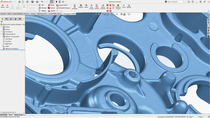
SOLIDWORKS, a Dassault Systèmes product, is one of the household names in the CAD software space. It is a great solution for commercial companies of different sizes, those looking to acquire skills in 3D mechanical CAD, design validation, and data management, entrepreneurs and startups, and R&D teams alike. This powerful software has been a dominant name in the market for the better part of three decades now, offering user-friendly features for 3D design and engineering.
SOLIDWORKS has tools for 3D modeling, electrical schematic design, and also features for creating 2D drawings of parts and assemblies of varying complexity. SOLIDWORKS also offers functionality for things like motion and stress analysis, estimating costs, design validation for manufacturability, and, being cloud enabled, also offers various collaboration and version management tools. You can use simulation to analyze a model’s physical real-world behavior in various application scenarios.
Siemens NX
Perpetual license price available from vendor on request.
Windows, Mac, UNIX, Linux
- Advanced and comprehensive toolset
- Easily works with multiple formats
- Works with CAM files that can be used for CNC machining
- Customizable: plug-ins can be built to extend functionality
- Has modules for different purposes: sheet metal, free-shape modeling, kinematics, etc.
- Steep learning curve
- Expensive
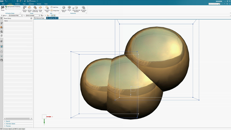
Siemens NX is widely considered to be the industry leader in mechanical engineering software. Looking at the list of capabilities it offers, it’s easy to see why. Its functionality extends beyond simple CAD tools to include comprehensive solutions for collaboration and communication, as well as advanced features for engineering analysis, design, and things like topology optimization. There is a whole roster of features that should cater for even the most demanding and complex projects, tools for freeform surface design, parametric solid modeling, routing, mechanical piping, and electrical wiring design are just a few of the many tools this software has to offer.
Dassault CATIA
Available from vendor on request
Windows and certain UNIX systems
- Feature rich
- Easily works with multiple formats
- Functionality-based licenses help reduce costs for those who do not need the entire set of features
- Cloud tech offers flexibility and scalability, and facilitates collaboration
- Expensive
- Unconventional UI can be confusing for those used to other systems
- Reported complaints about inadequate customer support
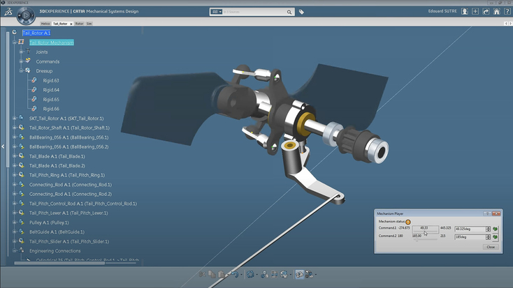
Image source: 3DS_CATIA/YouTube
Dassault Systèmes’ CATIA is another industry favorite when it comes to CAD software for mechanical engineers. The product website calls it the world’s leading product design and experience solution, and offers a raft of features to back up its claim. Along with the usual CAD modeling features you would expect, it offers optimization features to enable you to finetune parts or assemblies, resulting in lightweight objects – something that is critical in automotive engineering. There are tools for minimizing part weight, improving stiffness, reducing material usage, and subsequently, costs.
Those primarily interested in reverse engineering or industrial design will be particularly pleased by something Dassault describes as a shift from Computer Aided Design to Cognitive Augmented Design. CATIA has the ability to propose a design based on a given design space, and optimize it according to the manufacturing process – milling, casting, forging, or 3D printing, for example. You simply provide CATIA with some design specifications – the boundaries of the design space, the loads and forces you expect, the material – and the software generates a topology-optimized concept that you can tweak, validate, and collaborate on, within the software, and with other teams.
Fusion 360
$495 / year
Mac, PC
- Relatively inexpensive
- Supports collaboration
- Easy to use
- Lacks more complex parametric modeling tools
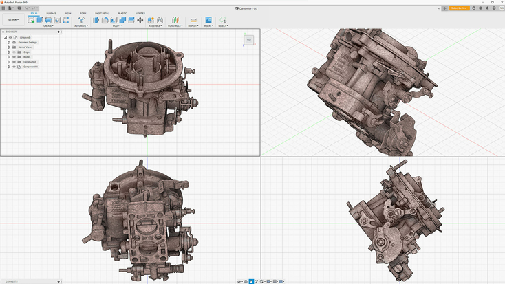
Fusion 360 is a popular CAD software developed by Autodesk. It is a cloud-based program, which makes it great for collaboration within and between teams, and also provides a means for version management of projects. It has features for solid, mesh, and parametric modeling. You can create CAD models, add details to mechanical drawings, and even do 3D animation and rendering. Fusion 360 also has 2D drawing tools, simulation features, and can support turning and milling if you are using Computer Aided Manufacturing.
How to convert 3D scans to CAD
3D scanning brings unique benefits, and adds efficiency, versatility, and quality to a variety of workflows. Rapid data capture speeds, convenience in hazardous and hard-to-reach areas, contactless data capture, high level of detail and lack of human error and omissions in measurement, and the cost and time savings that this efficiency brings.
Although professional 3D scanners can produce high-resolution 3D models with astounding accuracy, this scan data is not always immediately usable for engineers. The next step is to be able to take the models apart, analyze them, and modify them. The issue with the point clouds or mesh data that 3D scanners output is that the models are monolithic blocks – like statues or sculptures, whereas engineers need parametric models – models defined by mathematical formulae and parameters. This is where scan-to-CAD software comes in.
Scan-to-CAD software takes 3D scan data and uses it as a reference to create a CAD model that can then be easily modified. This is much more efficient, and more accurate, than starting CAD design from scratch. Highly accurate 3D scan meshes provide geometric information like dimensions and cross sections. Using 3D scan data as a reference for CAD modeling thus brings a higher level of effectiveness and accuracy to the process.
There are several scan-to-CAD solutions on the market. Here are a few of the top options:
Artec Studio
- Annual subscription:
- Lifetime license with free updates:
Windows, macOS via BootCamp
- Impressive set of tools for inspecting and editing 3D meshes
- CAD functionality expanded with each new software release
- Seamless scan-to-CAD workflow, compatibility with leading CAD software
- Can’t be used for creating models from scratch
- For advanced reverse engineering operations, you might want to opt for Geomagic products
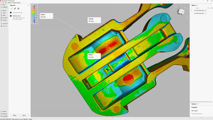
A 3D scanning and 3D data processing platform updated with improvements, new features, and new technology every year, Artec Studio simplifies and enhances your engineering processes. The software provides powerful scan-to-mesh workflow automation, an AI neural engine for enhancing data capture for even higher quality meshes, and it has the ability to handle extremely large datasets – up to 500 million polygons. Additionally, Artec Studio offers powerful photogrammetry features. You can import images and use them to generate point clouds for use in measurement-related applications, or as reference data for 3D scanning large objects and scenes.
Most notably for mechanical engineers, Artec Studio is designed to make the scan-to-CAD process as seamless as possible. You can easily convert scan data into CAD models for reverse engineering or inspection, or for use in animation and CGI. Fitting CAD primitives to 3D models and precisely positioning them is painless. The software slots seamlessly into most workflows. You can export STEP files directly to SOLIDWORKS, or complex meshes to Geomagic Design X or Geomagic for SOLIDWORKS, bringing even more flexibility and versatility into your application scenario.
Geomagic Design X
Windows
- Ultimate solution for turning 3D scan data into feature-based CAD models
- Will probably meet any reverse engineering need you may have
- Comes with quite a high price tag – but for that you get the best of the best
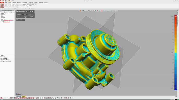
Geomagic Design X enables you to create 3D models from 3D scans. This greatly simplifies the process of reverse engineering by making it easy to create editable digital copies of real-world objects. Design X can quickly process large data sets and produce 3D models in different formats – solid, surface, and mesh. The models created in Geomagic Design X can be exported, with their full design history, to other CAD software for more complex operations.
Geomagic for SOLIDWORKS
On request
Windows, macOS
- Opens directly in SOLIDWORKS
- Automated wizards easily create accurate sketches, surfaces, or feature-based editable models
- Nifty workflow for NURBS and freeform shapes
- Can be a bit hard to master for a novice
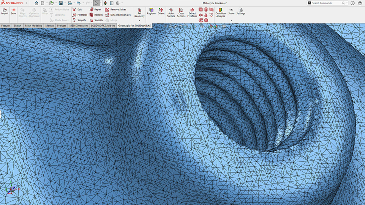
Geomagic for SOLIDWORKS is intended to slot directly into SOLIDWORKS and bring Geomagic capabilities directly available from SOLIDWORKS. Geomagic for SOLIDWORKS helps refine the scan-to-CAD workflow and, according to the product website, brings considerable efficiency benefits, including up to 50% faster total reverse engineering workflow compared to general CAD on organic parts.
And there you have it! Ultimately, the right software for you comes down to what you need it for, what features are essential to your workflow, and what you’re willing to invest. Try these options out – we hope you find what you’re looking for, and are off to greater solutions and success!
Read this next
More from
the Learning center
If you’re wondering whether you might need a CAD system for your company’s or clients’ design or engineering needs, read on. What may seem like a sizeable investment amidst a dizzying array of choices can prove to be one of the greatest decisions you make, saving you untold volumes or time, energy, and expenses. This article serves as an overview of today’s CAD systems, what types of challenges they help solve, as well as how 3D scanning powerfully enhances CAD workflows, for inspection to reverse engineering and beyond.
For decades now, companies in need of highly accurate measurements have often turned to CMMs (coordinate measuring machines). But more recently, another solution has entered the playing field, one that offers many compelling advantages over CMMs, including go-anywhere portability, ease of use, surface-safe/no-contact needed, 10X-50X faster measurements, and more.
After reviewing the top 3D scanner lists available on the Internet, we noticed that most don’t include information about the key parameters of the objects you need to scan. Important categories such as object size and the application(s) you’ll be using the scanner for are not covered. This review aims to fill this gap and help you find the best 3D solution for your project.


